Making parts that fit together is really one of the key deliverables for a full service product development consultancy. Sure people want it to look good and pass all of the regulatory specifications, but it absolutely has to be able to be assembled and fit together well, consistently.
Often where things first go awry is in the absence of deciding how the part break ups and parting lines will be, where are the critical or controlling fit ups or fitment features needed, and doing a reasonable tolerance analysis to understand the challenge ahead. In all the excitement that is product development, these key fitment details cannot be overlooked, but often are.
Part break lines are actually a key design feature which can enhance a product’s look, but they can also hurt it if they are over done or needlessly burdensome. Things to keep in mind that are driving parting lines may be behind the scenes of what the product looks like on the outside, or they might be driven by color and texture breaks in the outer skin, or even used to communicate interaction zones.
Manufacturing decisions can sometimes drive part line details as well. Molded parts are lower cost to produce if the tool’s metal core, the portion of the tool that forms the inside of the plastic part, can be pulled straight out of the inside of the plastic part, without additional side action, slides or lifters in the tool. Part seams in the middle of primary visual surfaces or contact points with the user are also usually unwelcome. Elegant solutions usually come when the whole product development team (designer, engineers and manufacturers) come together and discuss the part break up early on.
Additionally, keep in mind, injection molded parts, especially as they get larger, will be inclined to have shrink and warp, post injection cycle, so two parts coming together only compounds this. If the parts are rigid then ribs and overlaps at the meet up points are more challenged to pull the two parts into alignment. The longer or more complex the seam along which the two parts meet up at, or the more tightly they are intended to fit all complicates things, making it hard to deliver on repeatable, high quality products, and that is before a third part is added to the junction. Yes, tight review of the individual part geometries and good mold design with mold flow analysis can help mitigate part distortion, but not eliminate it, and some designs have part features that are needed or desired that will be pushing the limits on injection molding anyways. So no matter how good the parts come together in the virtual world, the real world will present other challenges, and usually a few that will not be anticipated.
This is where deciding on where critical fits are really needed and deciding whether to go down the path of needless complexity without value is crucial. Often times a reveal (planned and controlled gap) between two parts, or overlapping of surfaces of two parts, or localized positioning ribs, and more straight forward part to part borders can go a long way to delivering good looks, lower cost and shorter time to market for the new product. If a zero reveal, or line to line fit up is truly needed for the look then the team should face the added challenges right up front establishing key alignment concerns and control features, early molder review to identify warping in the parts, plan for additional part fixture for post mold form control, and the general added part cost increase hit to the bottom line.
All of these challenges may not be fully understood if due diligence is not done in regards to tolerance stack up early on. All parts will have a range, within which their size will vary, and assembling parts on parts will add up the variances, sometimes off setting one another, and other times making things worse. Additionally, just finding tolerance study results that only show how bad things can vary is not where it should end. There should be a thorough review and thought put into where misalignment could be designed out or made less of an issue with manufacturing options. We find many companies, new or established, actually have not performed thorough tolerance studies of their designs and they wonder why they have such variations in production. Properly accounting for part feature form and position, let alone considering reasonable expectations for part feature fabrication, are necessary for consistent quality products. In many cases the sheer number of parts expected to work together to achieve some alignment or finished look, as assigned by a never seen system engineer or marketing person, is blatantly unrealistic, and in some case there is still a needless discussion about just spending more money to make the parts to higher tolerances. This is not needed if some of the parts contributing to the tolerance stack up can be removed from driving fit up of the mating parts. If key frame work or other mounting strategies can be employed to better align part to part fitment. It may take a little more time in the design process but this will be nothing compared to the headache of inconsistent results during initial production and the delays associated with trying to fix things in the late stages of development.
Once a more straight forward set of design features and tolerance controlled interactions are in place, fitment of the enclosure parts, whether part to part, mounting features on sub-frames, or an assembly strategy emphasizing key fit up locations, it will still be important to have planned for appropriate clearances where needed and key part contact points to mountings surfaces to ensure the positioning. This is a bit like a 3D puzzle sometimes, but it is important to remember that for every line to line fit some other line to line fit may fight with it or drive the part out of position, and this may only happen when the part is on the large side or small side of its tolerance range. Having a strategy, again, where the parts come together with key touch off points and hard mounts is key, and many times these can be behind the scenes, so to speak, leaving visible a slight but consistent part break seam, overlap or reveal.
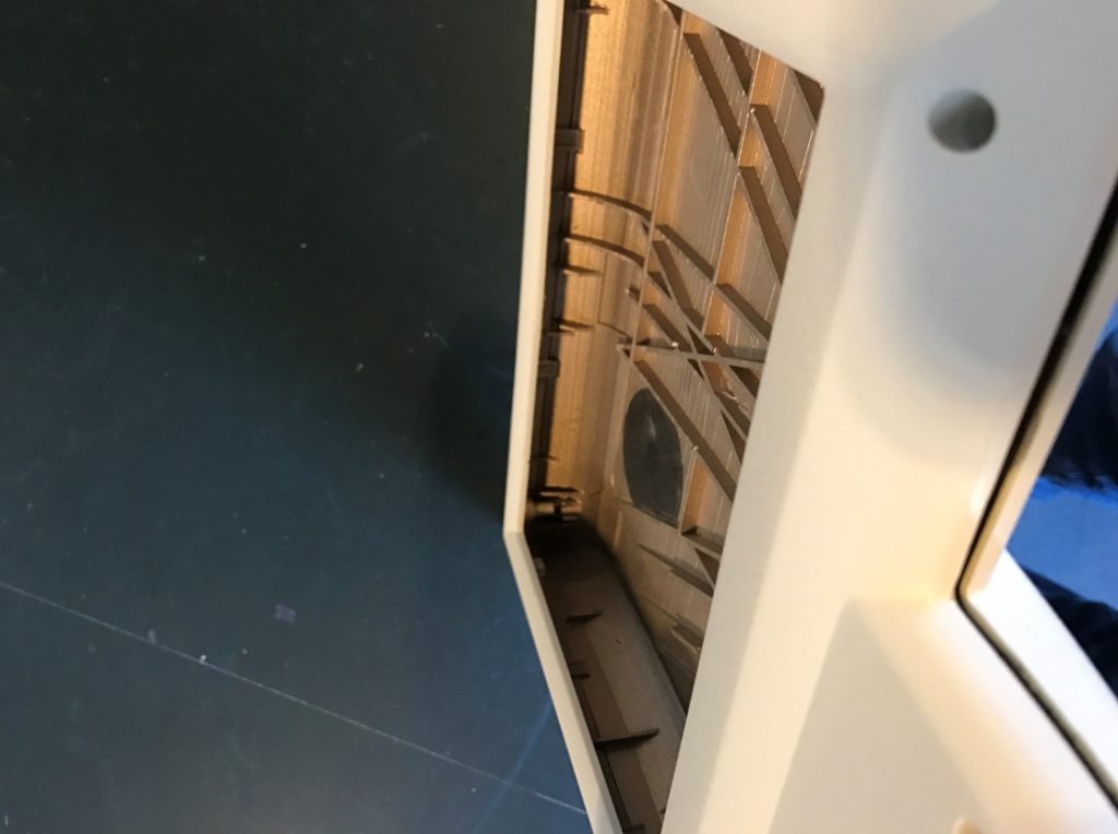
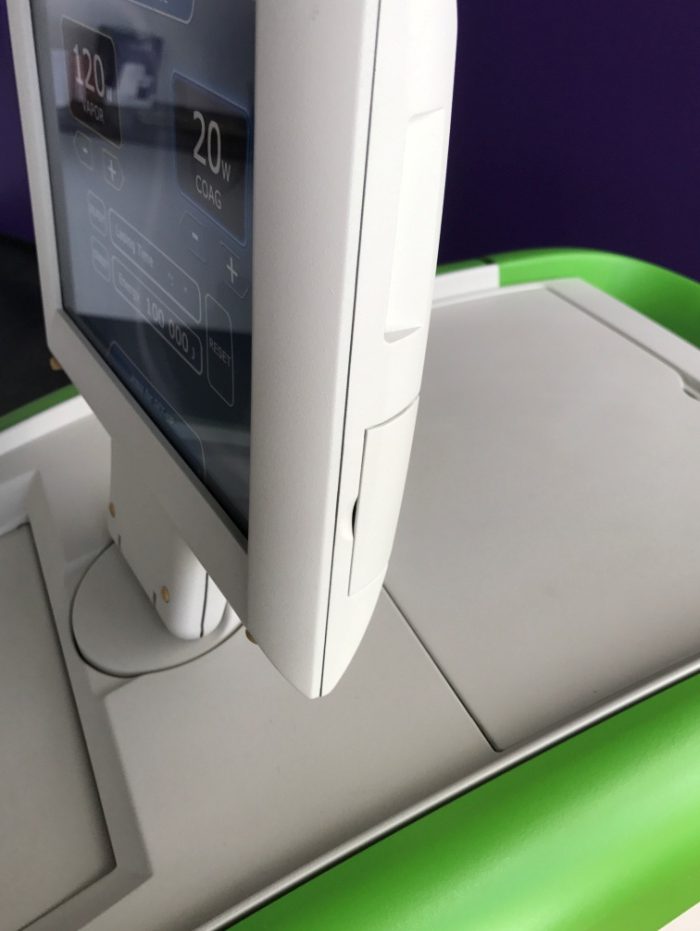
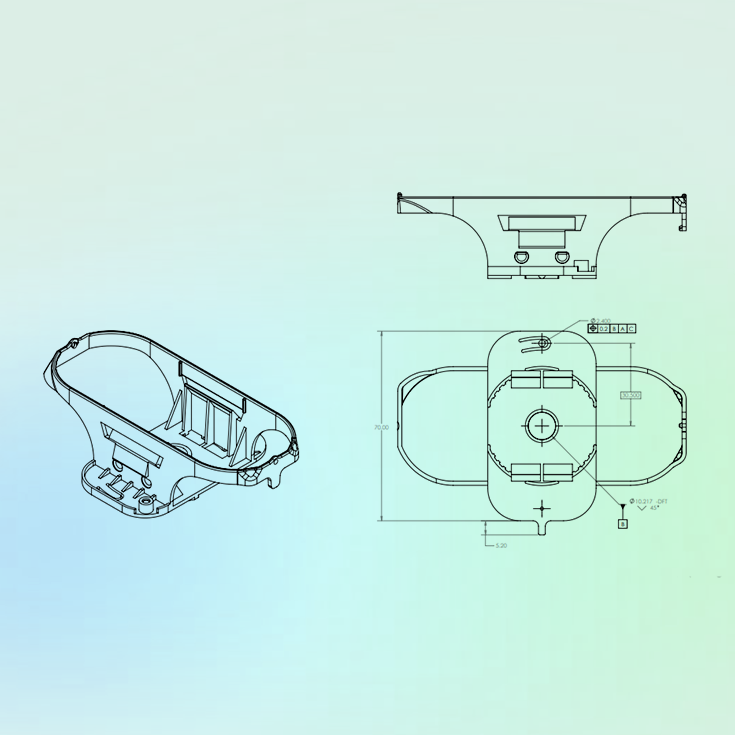
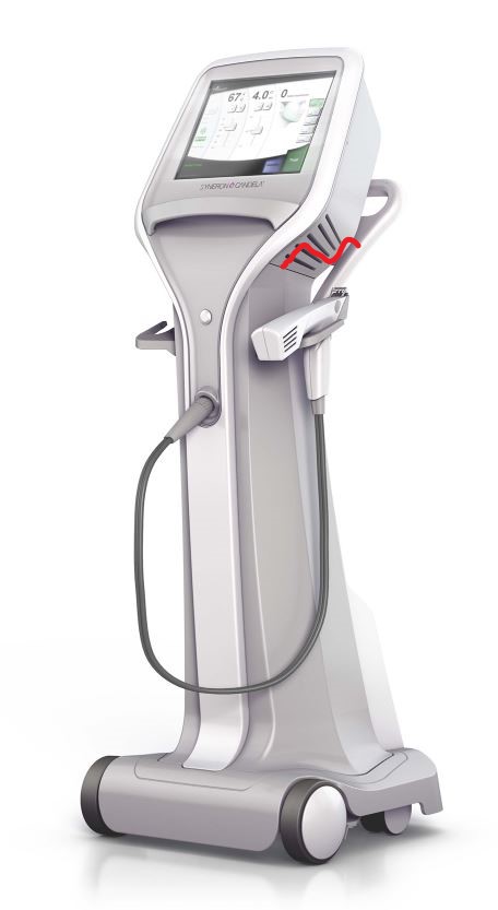
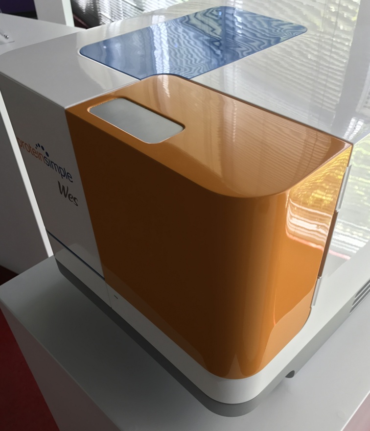
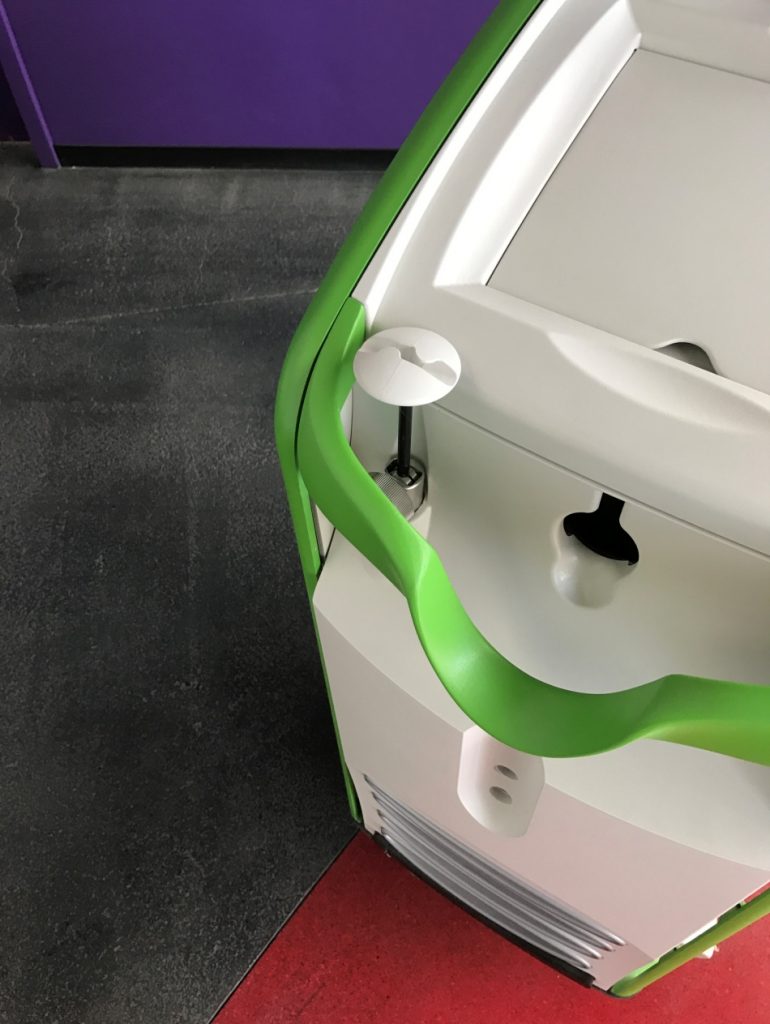
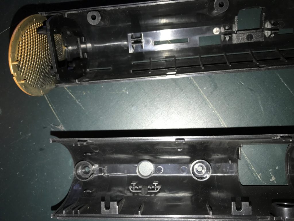
This custom touch screen enclosure had to have a smooth finish and be structurally sound to be steady during interfacing. Additionally, it had to be fluid ingress resistant. The injection molded outer housings relied on several inter looking ribs, snaps and reveal overlap as can be seen looking up into a housing in the right image. These features kept the sides and edges aligned and helped the out housing be more rigid when assembled.
There will still be possible injection molded part warp challenges with long seams, but slight, planned for surface insets, gaps and edge rounds on parts can hide these remaining imperfections even on assemblies that seem to have continuous surfaces with only slight breaks between the parts. You can produce a product with dozens of properly designed fitted joints, but your design team will only remember the one part to part interference that won’t align when it is first assembled.
Once your design strategy is decided on with your development team and the details have been worked through, your prototype build will be your chance to confirm proper fitment and ease of assembly in the real world. Expect to learn from your prototype, as a part is worth a 1000 pictures, but you will need to inspect your incoming prototype parts to make sure they actually are in specification to your design. And do not just inspect your parts where you find a problem as you look for the cause, but inspect them at any critical feature area as you do not want an out of specification part to confirm you design comes together well only to find in production that when the part is made correctly to specification it will not fit. Your prototype should be studied to ensure that your assembly strategy, locating features and tolerance range will repeatedly produce high quality assemblies as you move to production. It is also an opportunity to, “Walk in,” locating features and mounts to achieve the desired fitment to adjacent parts. We sometimes deliberately produce key locating features in a prototype slightly larger so material can be easily removed to learn what the best feature size will be for fit up. Of course for production molded parts the opposite is true as slightly under sizing a key fitment feature will allow the tool maker to remove material from the metal tool increasing the plastic part’s size to optimize fit. This is referred to as being “steel safe” as removing material from a metal forming tooling is much easier and cheaper than adding material. But this approach needs to be discussed during development with your tool maker and molder so they understand what the desired outcome of the plastic part is.
In all cases, having whole team involvement early should help make decisions regard fitment, quality, design, and meeting cost targets while eliminating lost time to market for the new product under development go much more efficiently. Clever design approaches can hide part junction irregularities and mismatch in joints while maintaining simple individual part geometry and dimensional control and at lower manufacturing costs if the assembly is considered from the beginning and the design is assessed for overall value to the client.