Quality is at the center of everything we design and develop here at StudioRed. Whether it’s related to form or function, ensuring parts are manufactured within specification is paramount to guaranteeing quality for our clients. This is accomplished not only through the physical design of the parts but also in the 2D drawings that accompany the designs when going to production. The 2D drawings are the contract which the engineering, manufacturing, and inspection teams mutually sign when it comes to producing parts – we are all agreeing that the dimensions, materials, finish, etc will all be strictly met.
Sure, we often send out 3D models, but these are theoretically perfect and don’t account for variations within manufacturing processes. Without 2D drawings, there would be no method by which to communicate the dimensions and features we care most about while also accounting for the inevitable imperfections in manufacturing. Now that we know we need a 2D drawing that highlights key dimensions and features, how do we go about actually communicating them to manufacturers? This article serves as an introduction to Geometric Dimensioning and Tolerancing (GD&T), a technique for effectively communicating intent in your drawings.
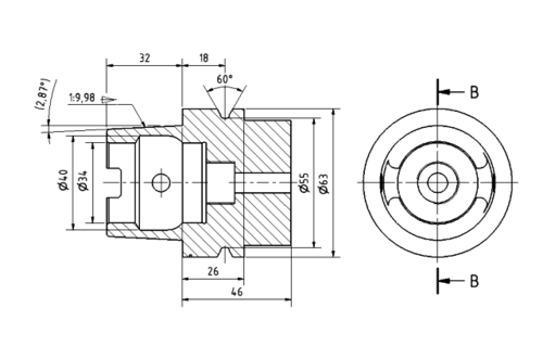
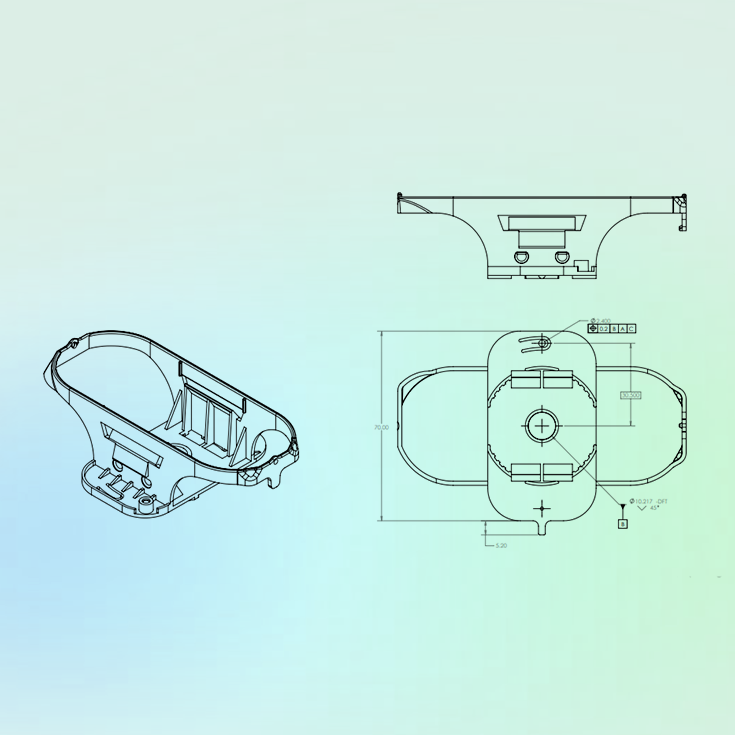
Typically, engineers will make their 2D drawings using only simple conventional dimensioning as shown above. These represent the allowable variation in a physical dimension. For example, these would help qualify the thickness of a part, the dimension between two holes, the height of a boss, etc. Unfortunately, exclusively using linear tolerances has its limitations.
Especially for parts which need very tight tolerances, the risks of using only linear tolerances include increased manufacturing costs and lead times. We as engineers should keep tolerances as large as possible while still ensuring intended form and function of the part. Then, how do we ensure critical dimensions and features are within specification without needlessly bloating the effort, cost, and time associated with manufacturing and inspecting a part?
How do we best communicate critical dimensions and features?
The answer lies with Geometric Dimensioning and Tolerancing, or GD&T for short. The ASME Standard Y14.5, GD&T is a great way to ensure the vendor is creating a high-precision part that looks and functions exactly how we and the client intended it to. From a high level, it is a language of symbols and standards that allows us to better define how significantly part features can deviate from their intended geometry. A number of these symbols can be seen in the below image:
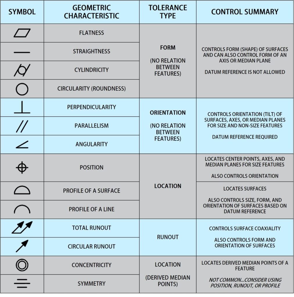
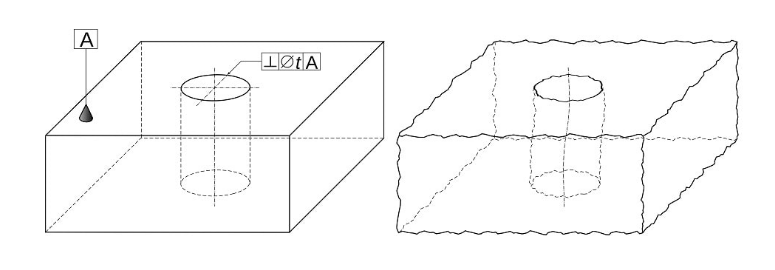
The GD&T technique is split into the geometric aspect and the tolerancing aspect. It is not a question of which one is more useful, but how to use both in tandem to effectively communicate design intent. The geometric approach can be broken down into three main categories: form, orientation, and location tolerances. Form tolerances control the “geometry” or “shape” of a feature and often modify size. Orientation tolerances control the angle of a feature, often modifying location. If applied to surfaces, they can also control form. Lastly, location tolerances control positions of center points, axes, and median planes. They can also control form and orientation based on application. Ultimately, GD&T focuses on the function of the part – how critical surfaces, holes, pins, etc interface with each other.
Also integral to the geometric approach are datums. A datum is a theoretical exact plane, axis, or line that GD&T tolerances reference. A datum feature is a tangible surface – planar or cylindrical – on a part where the theoretical datum is constructed. To make it easier to understand, datums are perfect and datum features are not. It is good practice to choose datums, and therefore datum features, which are important to the intent of the part and thus make sense to reference to. The inspection teams will then use these datum features as the primary means by which to inspect the part.
An Example of When GD&T Is Useful
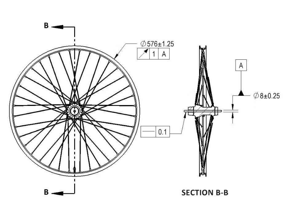
At this point, it might be helpful to present an instance when an engineer might opt for a GD&T approach over just conventional linear tolerances. Take a simple bicycle wheel, for example. We would of course be particularly concerned about the radial trueness, or “roundness”, as this helps determine how smooth the ride will be. If we were using conventional dimensions, we would list the nominal diameter of the rim, as well as a tolerance range. Because we care a lot about the radial trueness, the tolerance on the diameter would have to be quite tight. This would be both expensive to achieve and difficult to inspect. This approach also doesn’t account for center axis location relative to outside diameter.
However, there is a better way – GD&T allows us to use its runout control, which controls both location and form. We would callout a circular runout tolerance on the outer rim surface relative to a datum, the central axis of the wheel. This approach allows us to loosen the diameter tolerance while still controlling radial deviation relative to the center axis. We know that this is what we care most about for function, not the diameter of the rim. In this example, it is clear the benefit of the GD&T approach over basic size dimensions.
The Potential Risks of Not Using GD&T
You also might be asking yourself what the risks are if you don’t choose to implement GD&T practices in your drawings. Sure, you may have to pay a bit more or wait a bit longer, but otherwise what’s the concern? Notably, the risk is that parts may well meet all the dimensional tolerances on the drawing but not function/look as we intended. This is because without GD&T properly implemented, parts can have ambiguous instructions for inspection. Early on in StudioRed’s existence, before we had fully adopted GD&T as our standard, we had a few instances that exemplified this issue.
One that comes to mind is a large flat injection-molded plastic panel that lived on the side of a medical cart. We dimensioned the panel in all the obvious ways: overall dimensions, thickness, height of bosses, etc. However, we did not control the shape of the panel itself – i.e. a flatness callout or equivalent. This meant that the thickness, length, width, etc could all be in spec, but the panel could be warped enough that it would not fit in the context of the assembly. The inspection team would not even check this since it wasn’t explicitly called out on the drawing. This ended up being the case, and the tooling had to be modified. The tooling change was expensive to rework and the client had to wait for their updated parts. Today, we champion the principles of GD&T and implement it as often as we can.
As you can see, there is quite a bit to lose if you don’t use GD&T and a lot to gain if you do. This article is not exhaustive, as there is certainly more to learn within the subject – bonus tolerance, Rule #1, modifiers, and more. All of these affect how the drawing is interpreted and how the manufactured part is inspected. Due to the length of this post, we will not delve into all the details, but there are plenty of resources to help inform you on how to implement GD&T in your part drawings. Start using it today to cut down manufacturing costs and lead times!