In product development with injection molded parts we all want good looking products. And in business we want the project to proceed smoothly as there never really is time, and in turn money, for glitches and delays. So finding a big sink marks right there on the front A surface of your first article injection molded part, and it is supposed to have a shiny finish in production as well, can lead to the sinking feeling of how to fix this and how to fix it fast.
What to do? You could glue the product’s logo badge over it but that is already planned to be located elsewhere and hides the injection molding gate for the part. Maybe another badge? There is a better way to fix this both in the injection mold processing and in the part design.
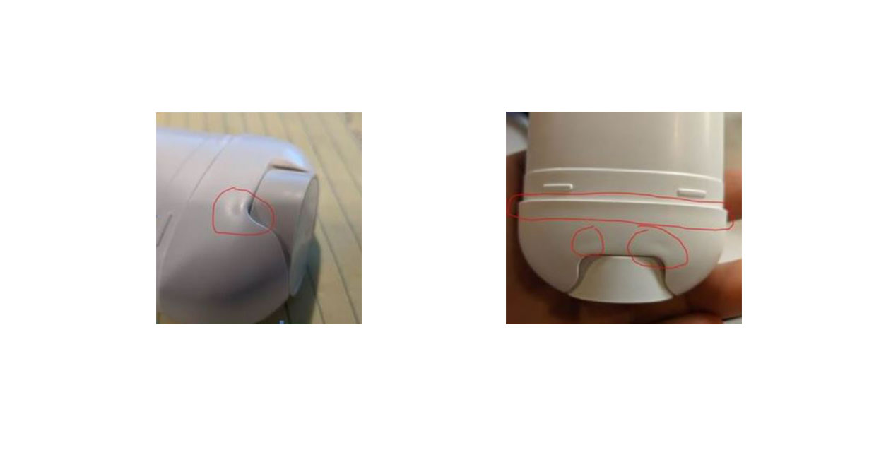
So why do sinks happen? Differential cooling in the part’s injection molded plastic material, usually in a thick portion of the plastic part’s wall, like where an interior rib or boss joins the wall, will draw in material as the middle of the thick section cools last, leaving a dimple on the opposing side. This looks more pronounced on smooth, shiny surfaces, especially of darker plastic colors.
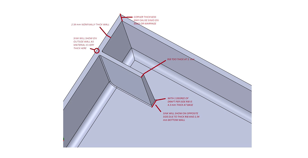
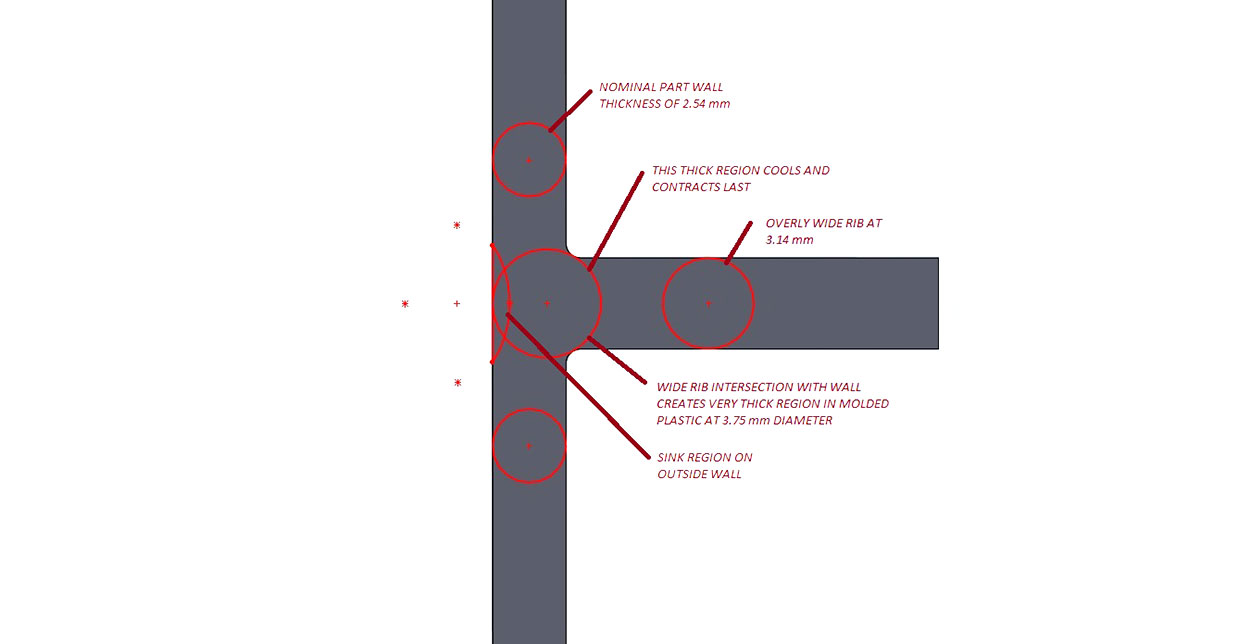
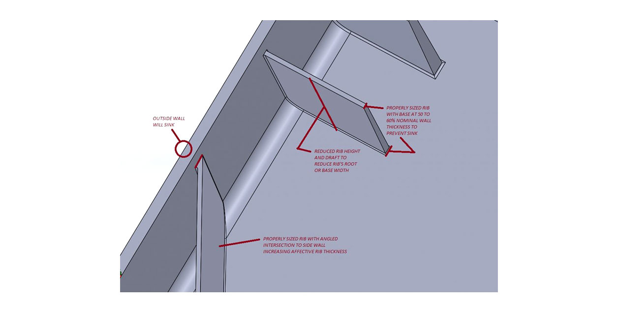
Where two outside walls meet or where angled surfaces touch off on an otherwise properly sized rib at a “baloney cut” can cause sinks too. Following some general recommendations on internal wall and rib thicknesses, staying at 50 to 60 percent of the nominal outside wall, can go a long way to help avoid thick spots in the injection molded part, and in turn sink flaws.
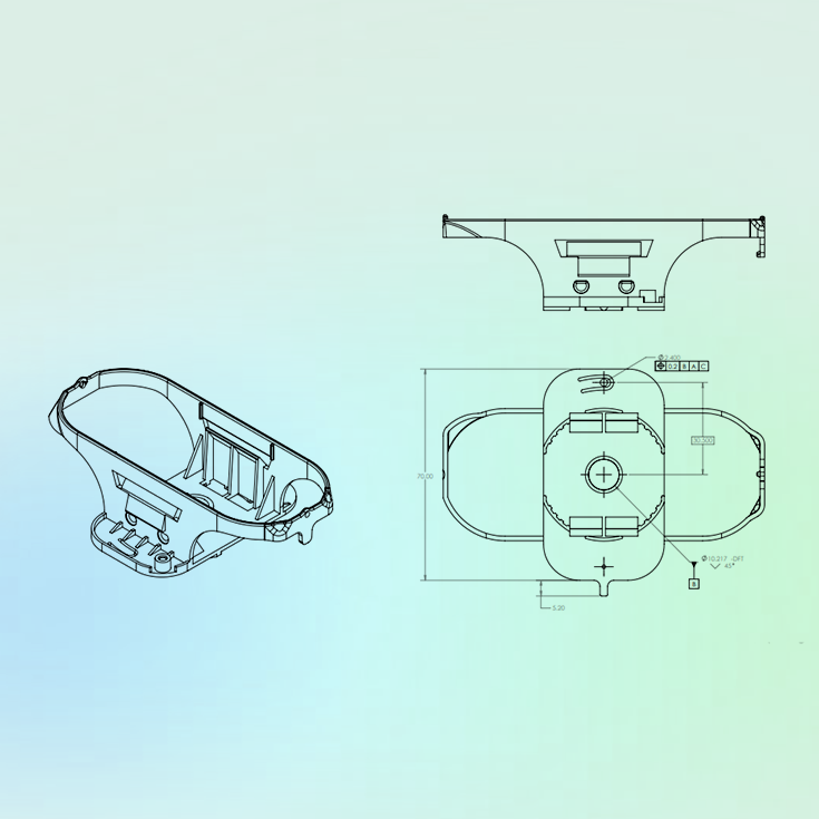
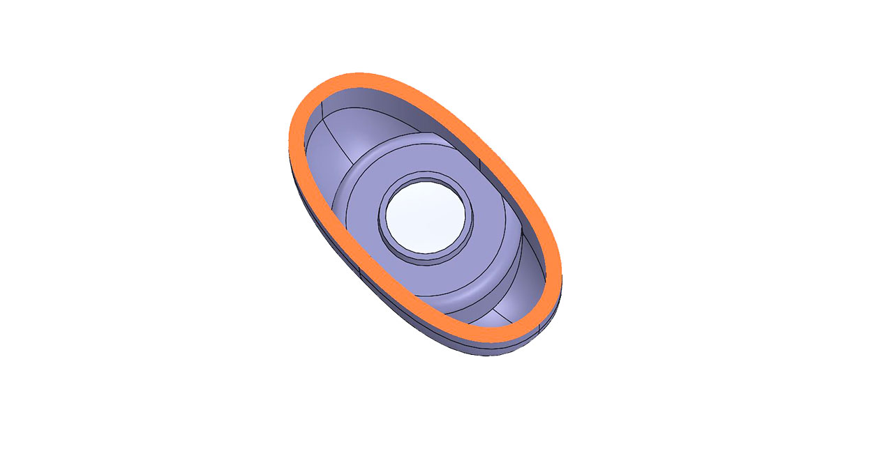
However, in more complex shapes and transitions in an injection molded part’s design, thick sections can get missed during development. Additional coring may be needed for the injection molded part in more obscure feature intersections. The shinny white dispensing canister base shown above had generally common wall thickness without heavy internal ribbing.
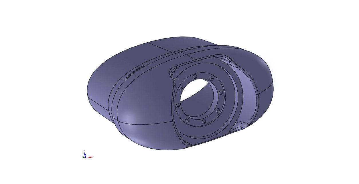
However the lower counter bore for the thumb screw created angled wall intersections that caused visible sinks. Close examination of the exact location in cross section revealed a convergence of features and material.
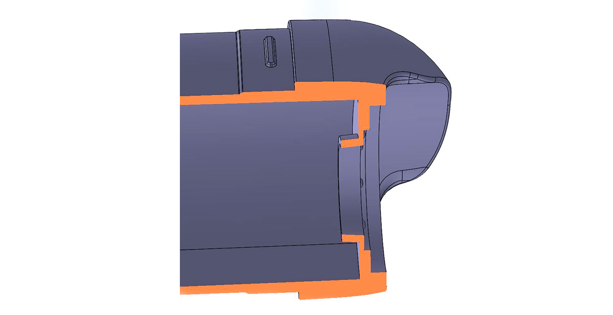
The features that created this thick section were not easy candidates for thinning, moving or eliminating to maintain the product’s small size and function. And sinks on the outside were unacceptable.
Slight inside coring features added to the core of the mold tool steel relieved some of the material in the injection molded part for the next article run.
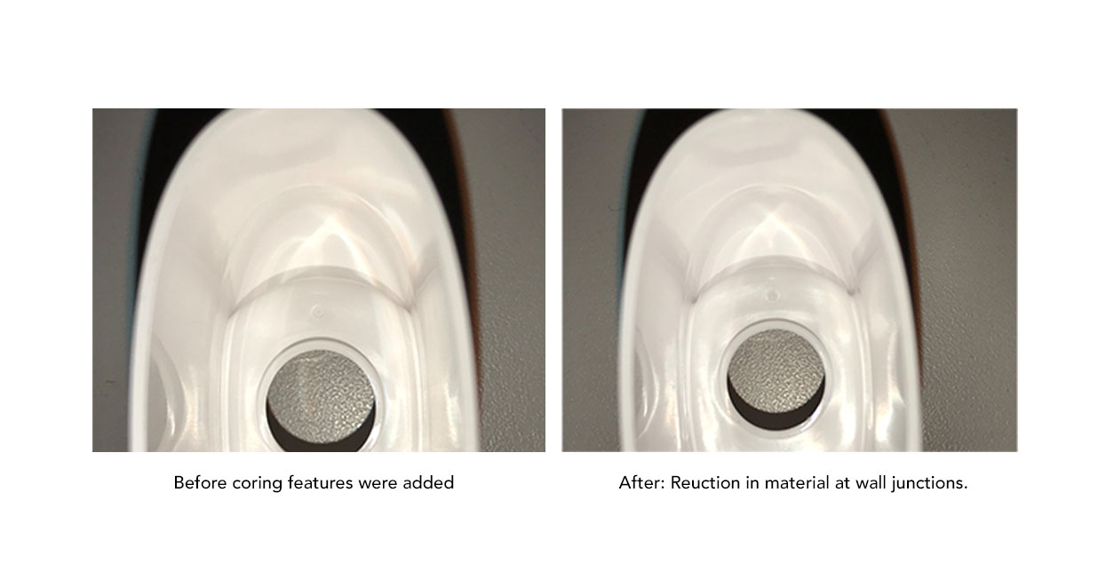
This along with working with the molder to extend cycle time (cooling in the mold) and process refinements yielded a flawless and functional part. Close coordination allowed things to be resolved quickly.
Bosses also pose a challenge in injection molded parts as they are critical for assembly. They can be thought of as conical ribs. They need to be sized to work well with threaded fastener and have strength, but present many opportunities for thick regions if certain techniques are not followed. We will have more on bosses in a future discussion as they are an important design feature with many considerations, all on their own.
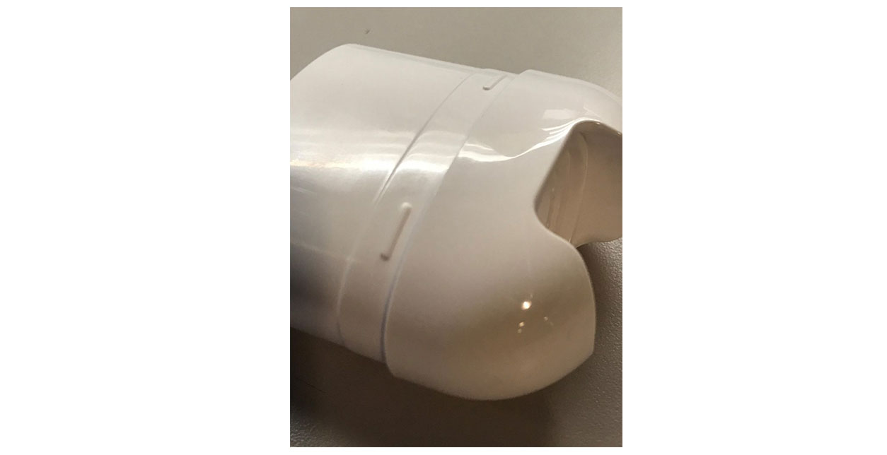
By using good injection mold engineering practices and the available 3D CAD tools, injection molded parts can be designed to minimize the risk of sink and other cosmetic flaws. And by working closely with a molder and tool maker as team members the injection molded part can incorporate refinements so the result is high quality, cosmetic injection molded parts that function as planned. Using this approach the time to market will be minimized.
So keep in mind recommendations for internal walls and ribs with regards to thickness and intersections. Minimize these features as much as possible and consider reducing their draft somewhat so their thickness varies minimally. Use CAD tools like thickness analysis and manually review complex intersections with the cross section tool for areas of possible sink. And then work with the molder on their mold analysis and recommendations. This may require further coordination during the first and second article part production, but close collaboration and attention to details will shorten time to market. And you won’t have to add another badge to cover up the injection molding flaw on the front of your part.
Links to: Part 1, Part 3, Part 4
